Dataset for the First Radio-Frequency Spectrum-Sharing Challenge (RFSSC)
Download our Datasets:
Please use the link below to download the datasets:Challenge Description Document, Exemplar Signals, Exemplar Scenes, and Challenge Test Scenes
These data were used in the First RF Spectrum-Sharing Challenge which was held in 2024-2025, culminating in announcing the winner AiRANACULUS on January 30, 2025. The first RFSSC was co-sponsored by the United States Air Force Research Laboratory (AFRL) and the National Security Innovation Network (NSIN).
Challenge Description
Overview
The first RFSSC was a data-centric contest open to US academic and industrial organizations intended to spur innovation in machine learning and signal processing for automatic radio-frequency scene analysis (RFSA). Analysis of RF scenes is a complex task involving various forms of signal-presence detection, parameter estimation, and modulation-type classification. Because the emphasis is on scenes, rather than on individual isolated signals, typical modulation classifiers found in industry, government, and the literature are insufficient. Moreover, the RF scenes used to test Challenge Participants are crafted to put pressure on known signal-processing and machine-learning limitations, such as excessive computational cost and lack of generalization.The Challenge setting is a fictitious spectrum-sharing problem, with three user classes, but the Challenge task is RFSA. The spectrum-sharing system rules are sufficiently complex, and the types of allowable user-class signals sufficiently large, to enable the generation of many different types of RF scenes--all of which still conform to the sharing-system rules-of-the-road.
Figure 1 is the Challenge logo, and it illustrates the basic concept of the sharing system: different user classes have very different communication and sensing motivations and requirements. There are three user classes in the sharing-system rules: Secondary Users (SUs), which have the lowest spectrum-access priority; Primary Users (PUs), which have the next-highest priority; and Urgent Users (UUs), which have the highest priority. The rules for accessing the spectrum are provided in the RFSSC Participant Guide document, which is available for download along with various data files. The hierarchy of user classes is illustrated in Figure 2.
Figure 1: The RFSSC logo. The logo encapsulates the core concept of spectrum sharing between multiple user classes with differing communication and sensing priorities.
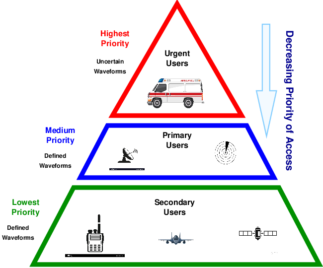
Figure 2: Illustration of the three-user-class spectrum-sharing problem developed in the RFSSC to enable principled generation of a great many RF scenes of widely varying complexity and analysis difficulty.
Basic Parameters used in the Challenge
On this page we provide a coarse overview of the Challenge and a detailed description of the data that can be downloaded. For a detailed description of the Challenge, read the Participant Guide document which is included in the available downloads.In all cases the sampling rate is 50 MHz.
Exemplar signals and exemplar scenes are short in temporal duration, one second or less.
Challenge test scenes are always 10 seconds long.
Scene Ground Truth: Ability-to-Transmit and Spectral Occupancy Matrices
In the RFSSC, Participants in the Challenge do not submit lists of detected signals, bounding boxes, parameters, and modulation-type labels. Instead, they submit five matrices per test scene:1. Spectral occupancy map for PUs
2. Spectral occupancy map for SUs
3. Spectral occupancy map for UUs
4. Ability-to-transmit for PUs
5. Ability-to-transmit for SUs
The dimensions of the matrix are determined by certain sharing-rule parameters (see the Participant Guide document), the sampling rate, and the scene duration. All five of these matrices are binary-valued. For the ability-to-transmit matrices, a matrix element is 1 if users can transmit in the corresponding time-frequency cell and is 0 otherwise. For the spectral occupancy matrices, a matrix element is 1 if the time-frequency cell is occupied by a user and is 0 otherwise. The matrices are illustrated for a crowded complex RF scene in Figures 3-5. The three ground-truth spectral occupancy matrices are combined into one for convenience in illustrating the concepts here.
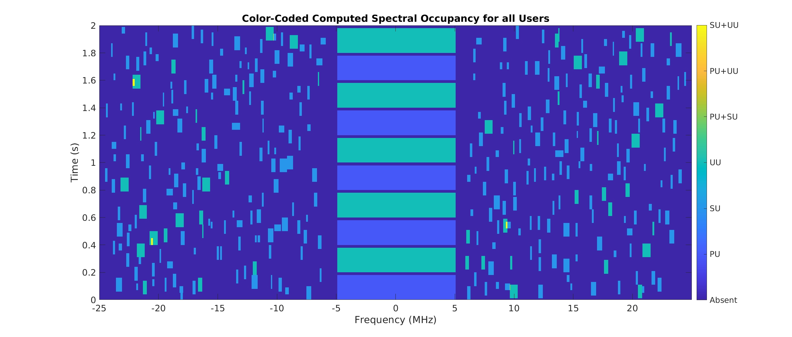
Figure 3: Ground-truth spectral occupancy for a typical generated RF scene in the Challenge. The bounding boxes are color-coded according to their user class. The sharing-system rules allow for cochannel situations, so that colors are needed to encode the simultaneous presence of two or more user classes in some scenes. These bounding boxes are not measured--they arise from computation of the occupied bandwidth of each signal given its parameters.
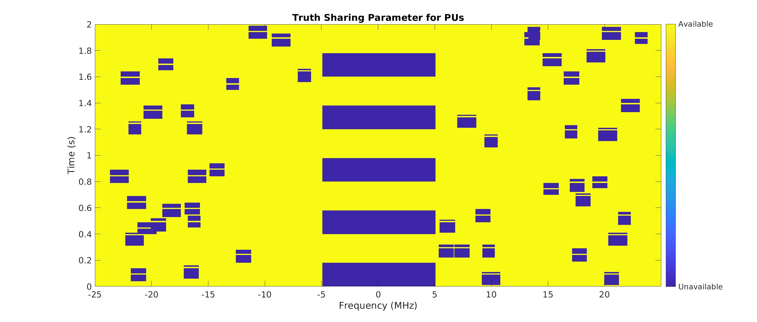
Figure 4: Ground-truth ability-to-transmit for PUs in the scene of Figure 3.
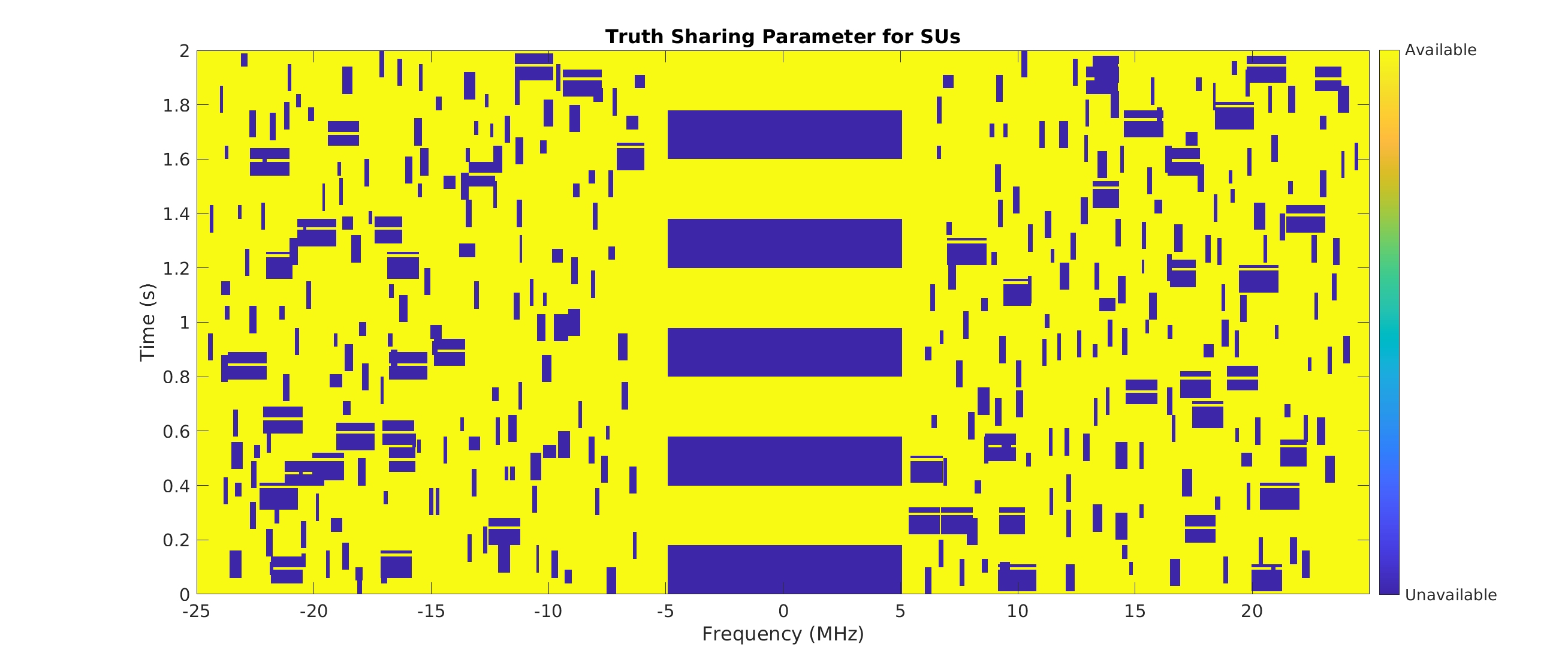
Figure 4: Ground-truth ability-to-transmit for SUs in the scene of Figure 3.
Experimental Setup
The first RFSSC featured only simulated radar and communication signals. To ensure correctness, the signals were independently generated at two different RFSSC Organizer locations, with independently developed simulators--one in MATLAB and one in C. The produced signals were cross-checked between the two locations, and all were subjected to detailed signal-processing verification steps.The scenes were created by first developing a textual description of each involved signal, which includes parameters relevant to the signal, such as the rate, filter rolloff, hop rate, and processing gain. Universally applicable parameters are the power level, start and stop times, and center frequency. The textual scene description represents ground truth, and is used as the primary input to the scene generator, which assembles the desired scene using the individual generated signals. The scene in Figure 3, for example, required a scene-description text file specifying 360 individual signals.
In future versions of the RFSSC, we will complement the simulated signals with SDR-transmitted and SDR-received signals of the same types, and with emulated time-varying propagation channels and radio impairments, taking a step toward more realistic RF scenes.
Dataset Description
The RFSSC dataset consists of the following elements:1. The Participant Guide document RFSSC_Participants_v6.pdf.
2. Exemplar Signals.
A set of noise-free short examples for each PU and SU type in the Participant Guide. This exhausts the PU and SU signals that can appear in a test scene. The signals are sampled at 50 MHz, are centered at zero frequency (complex baseband) and have durations of 65536 samples. This is long enough to perform validation signal processing, but not long enough to observe, for instance, multiple low-rate instances of a periodically transmitted synchronization sequence (which some of the RFSSC signals possess). They are intended to be used by Participants to validate their private construction of large training and testing datasets rather than as a training dataset themselves.
3. Exemplar Scenes.
A set of three 1-second scenes sampled at 50 MHz. These scenes contain just a few signals relative to the testing scenes, which contain many. Generally, the signals are disjoint in time and frequency, there are no propagation channels, and the SNRs are moderate-to-high. The purpose of these scenes is to ensure that Participants are able to properly construct the required spectral occupancy and ability-to-transmit matrices.
4. Testing Scenes.
A set of six 10-second scenes sampled at 50 MHz (see Figures 4--9). These are the scenes that were provided to the Participants in Rounds 3 and 4 of the RFSSC. All truth was withheld during the Challenge, but is provided here.
5. Spectral Occupancy and Ability-to-Transmit Truth Matrices
A set of five ground-truth matrices for each of the Exemplar and Testing Scenes is provided: three spectral occupancy matrices and two ability-to-transmit matrices, for a total of 9 x 5 = 45 ground-truth matrices.
Sharing-System Rules
The sharing system is fully described in the Participant Guide document RFSSC_Participants_v6.pdf.Signal Definitions
The mathematical definitions of the PU and SU signals are contained in the Participant Guide document. Definitions of the UU signals are withheld from Participants. This permits genuine unknown signal types to be placed in the RF scenes, stressing overly tuned signal-processing algorithms and machine-learning models that cannot produce an UNKNOWN or none-of-the-above decision type.The Participant Guide is RFSSC_Participants_v6.pdf.
Exemplar Signals I/Q Data
The exemplar signals are provided in files that conform to the sigMF data-file standard. Each exemplar signal is associated with two sigMF files. One is a text file containing meta data and the other is the sampled signal itself. The meta-data file strictly conforms to the sigMF standard, but contains only the length of the data in samples, the number format, and the sampling rate. The signal type, user class, and key modulation parameters are encoded in the file name.For example, an SU QPSK signal with 5.1 MHz symbol rate is associated with the two files
qpsk_s_5.1MHz_1.sigmf-meta
qpsk_s_5.1MHz_1.sigmf-data
The contents of the meta-data file are:
{
    "global": {
        "core:datatype": "cf32_le",
        "core:sample_rate": 50000000,
        "core:metadata_only": false
    },
    "captures": [
        {
            "core:sample_start": 0,
            "core:sample_count": 65536,
            "core:frequency": 0.0
        }
    ],
    "annotations": []
}
This indicates that the data are stored as complex floats ('cf'), 32 bits per float ('32'), and the bytes in the floats are ordered consistent with the little endian standard ('_le'). In other words, each complex signal sample is stored as a standard float
for the real part followed by a standard float for the imaginary part. This format is identical to the default binary output file format used by Ettus SDRs. Exemplar Scenes I/Q Data
The exemplar scenes are also provided as single sigMF data files--there are no meta-data files for the exemplar scenes. The ground truth is provided in terms of the spectral occupancy and ability-to-transmit matrices rather than in a sigMF meta-data file. The three exemplar data files are:exemplar1_50MHz_1sec_v2.sigmf-data
exemplar2_50MHz_1sec_v1.sigmf-data
exemplar3_50MHz_1sec_v1.sigmf-data
These are sigMF cf32_le data files, like the exemplar signals.
Exemplar-Scene Ground-Truth Matrices
Graphical depictions of the user-class-coded spectral occupancy matrices for the three exemplar scenes are shown in Figures 4-6. These truth matrices, and the true ability-to-transmit matrices, are provided as MATLAB .mat files:exemplar1_50MHz_1sec_v2.sigmf-data
exemplar2_50MHz_1sec_v1.sigmf-data
exemplar3_50MHz_1sec_v1.sigmf-data
and associated README files.
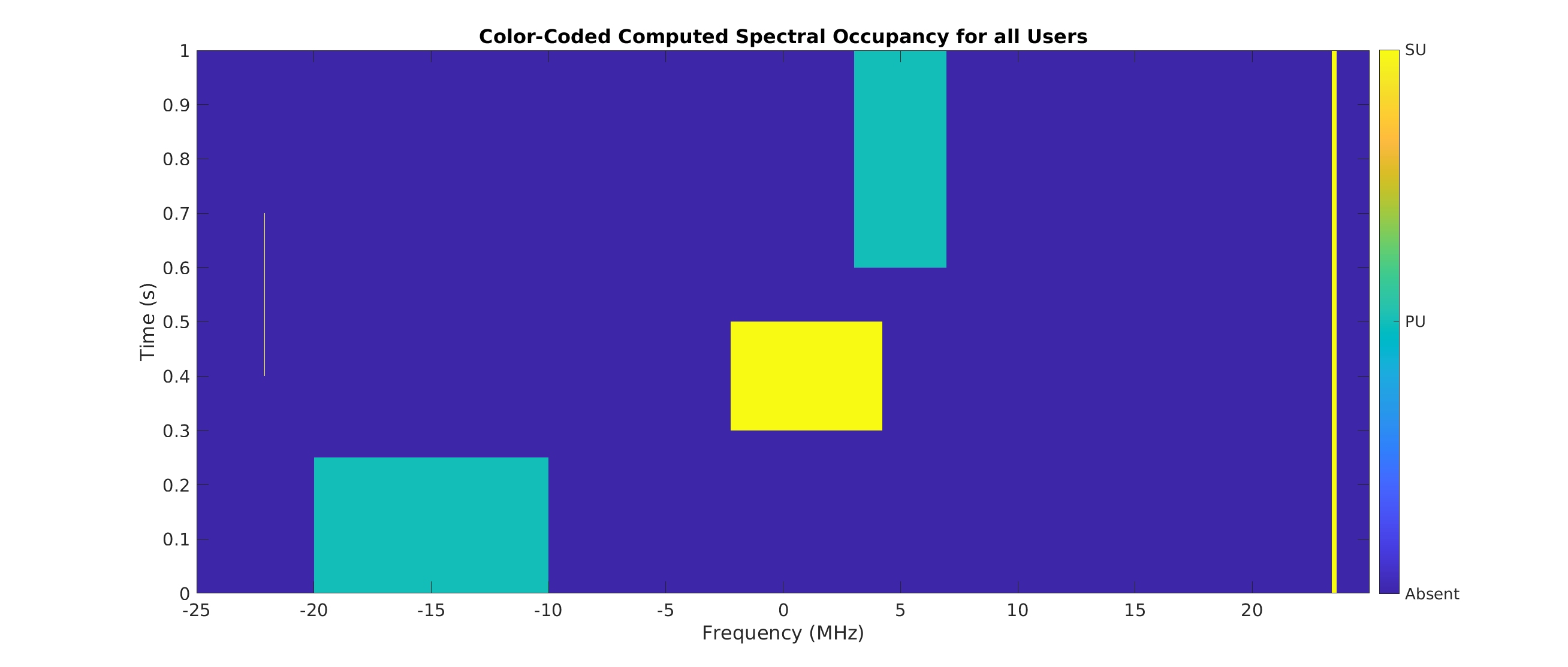
Figure 4: Exemplar scene 1.
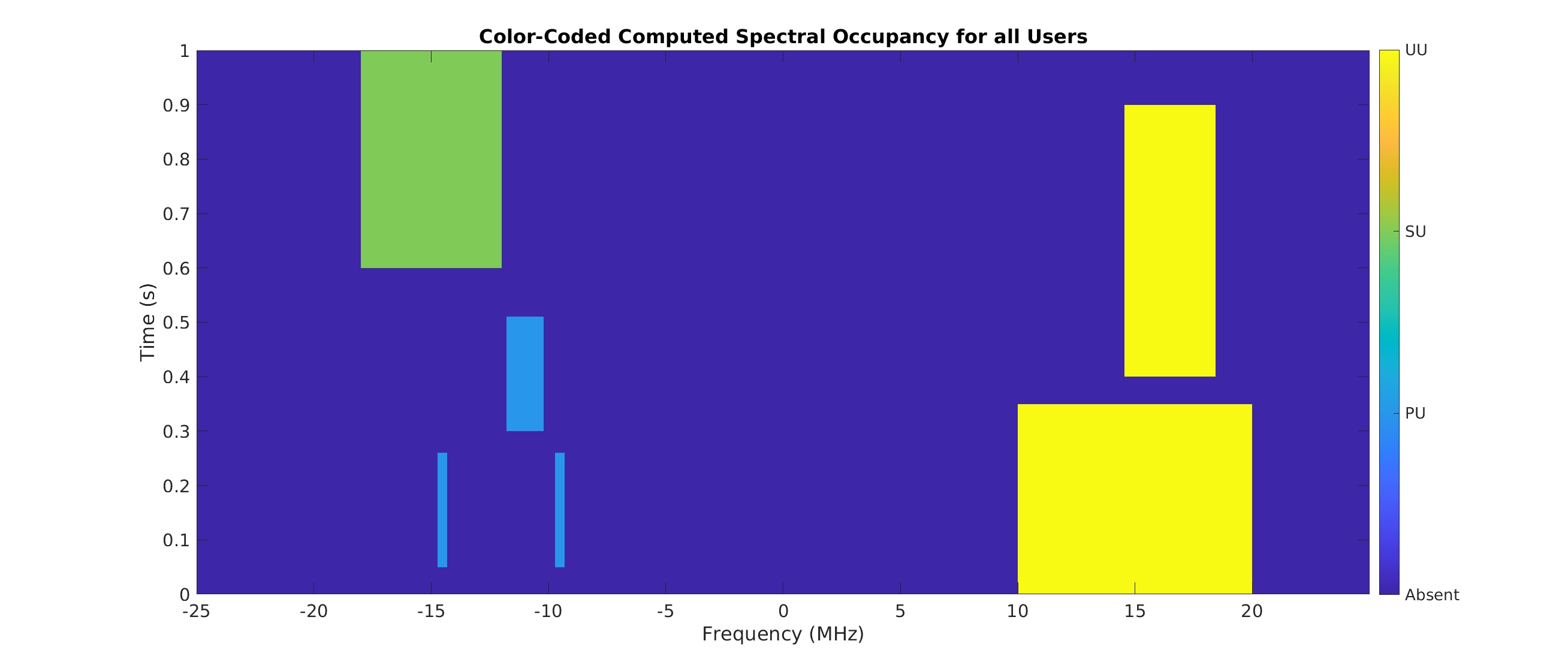
Figure 5: Exemplar scene 2.
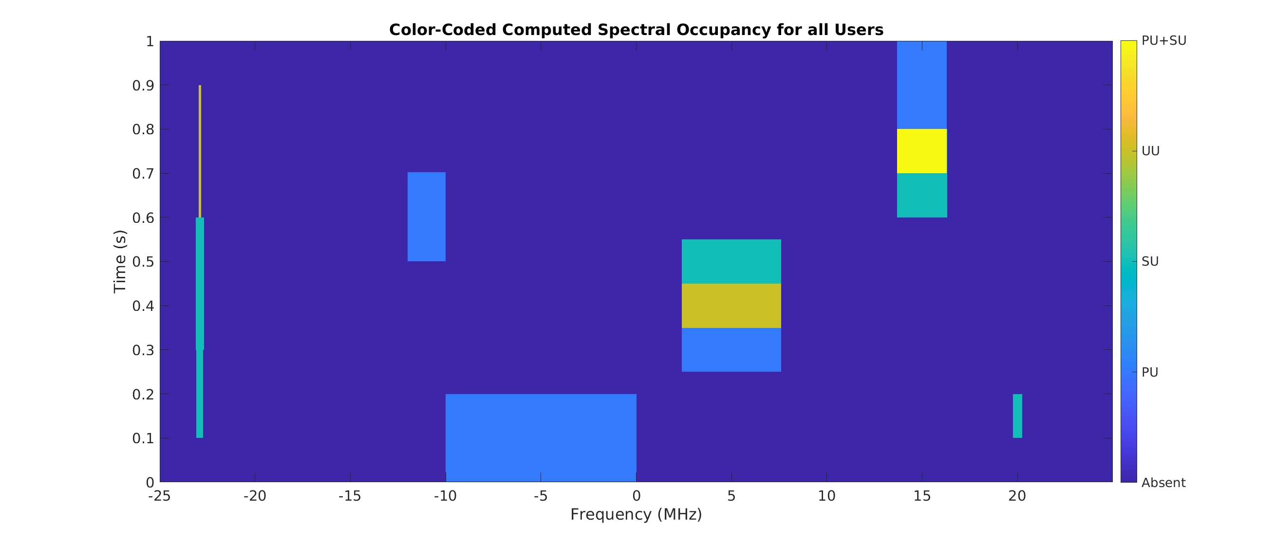
Figure 6: Exemplar scene 3.
>> scene_info

scene_info =

  struct with fields:

    sharing_params: [1×1 struct]
        sig_params: {1×5 cell}
                PS: [1×1 struct]
          num_sigs: 5
This structure contains the sharing parameters in sharing_params (see the Participant Guide document for definitions and details), the parameters defining the signals in the scene in sig_params, and the truth matrices in the PS field.
The sharing parameters are critical for a Participant because they influence the ability-to-transmit computation. For Exemplar Scene 1, the sharing parameters are
>> scene_info.sharing_params
ans =

  struct with fields:

              T_s: 1
              N_c: 5000
              B_c: 10000
              T_u: 0.050000000000000
              N_d: 5
              T_a: 0.040000000000000
              N_a: 500
              M_p: 50
              M_s: 50
              N_0: 0
              P_c: 0
              f_s: 50000000
              N_e: 20
              N_s: 100
              N_u: 4
          N_0_lin: 1
    num_subepochs: 100
     num_channels: 5000
       num_epochs: 20
            T_sub: 0.010000000000000
           N_samp: 50000000
The truth matrices are stored in the PS field:
>> scene_info.PS

ans =

  struct with fields:

           occ_vec: [1×1 struct]
         share_vec: [1×1 struct]
    sharing_params: [1×1 struct]

>> scene_info.PS.occ_vec

ans =

  struct with fields:

             PU: [100×5000 double]
             SU: [100×5000 double]
             UU: [100×5000 double]
         UU_mod: [100×5000 double]
     UU_timeout: [100×5000 double]
     UU_indices: [100×5000 double]
    UU_accesses: [5×20 double]
             BB: [5×1×4 double]
           tvec: [0.005000000000000 0.015000000000000 … ] (1×100 double)
           fvec: [-25000000 -24990000 -24980000 -24970000 -24960000 … ] (1×5000 double)
          Total: [100×5000 double]

>> scene_info.PS.share_vec

ans =

  struct with fields:

          PU: [100×5000 double]
          SU: [100×5000 double]
          UU: [100×5000 double]
    PU_final: [100×5000 double]
    SU_final: [100×5000 double]
The sizes of the spectral-occupancy and ability-to-transmit matrices is determined by the sharing parameters, which can vary from scene to scene. The truth occupancy matrices are scene_info.PS.occ_vec.{PU,SU,UU}, and the truth ability-to-transmit matrices are
scene_info.PS.share_vec.{PU,SU}_final. Another copy of the sharing parameters is also contained in the scene_info.PS field.
The time and frequency values for the rows and columns of the matrices are contained in the tvec and fvec vectors, respectively, and simple bounding boxes are defined by 4tuples in the BB field.
Challenge Test Scenes I/Q Data
The I/Q data for the six test scenes follows the same format at the exemplar scenes except the scenes are 10 seconds long instead of 1 second. The six scene data files are:tranquility_50MHz_10sec_v1.sigmf-data
masquerade_50MHz_10sec_v1.sigmf-data
sampler_plate_50MHz_10sec_v1.sigmf-data
bad_day_50MHz_10sec_v1.sigmf-data
emergency_50MHz_10sec_v1.sigmf-data
scanners_50MHz_10sec_v1.sigmf-data
and the associated sharing-parameter files are:
tranquility_v1_sharing_params.txt
masquerade_v1_sharing_params.txt
sampler_plate_v1_sharing_params.txt
bad_day_v1_sharing_params.txt
emergency_v1_sharing_params.txt
scanners_v1_sharing_params.txt
Challenge Test Scenes Ground Truth Matrices
The color-coded occupancy matrices for the six test scenes are depicted graphically in Figures 7-12. The truth matrices are supplied in the same way as for the exemplar scenes. The six MATLAB files are:scene_info_bad_day.mat
scene_info_emergency.mat
scene_info_masquerade.mat
scene_info_Sampler_plate.mat
scene_info_scanners.mat
scene_info_tranquility.mat
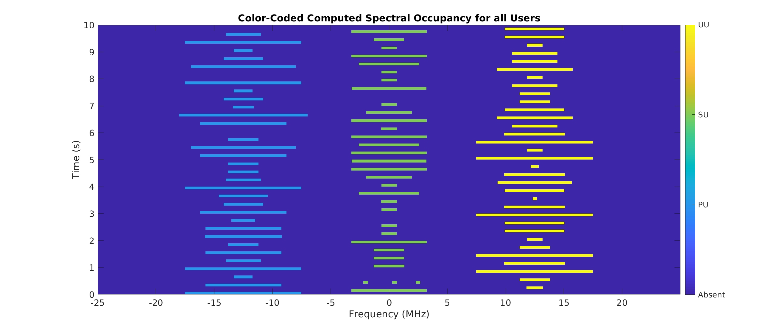
Figure 7: Tranquility. Designed to be easy. One signal is present at any instant, bounding boxes never touch, no propagation channel, moderate-to-high SNRs.
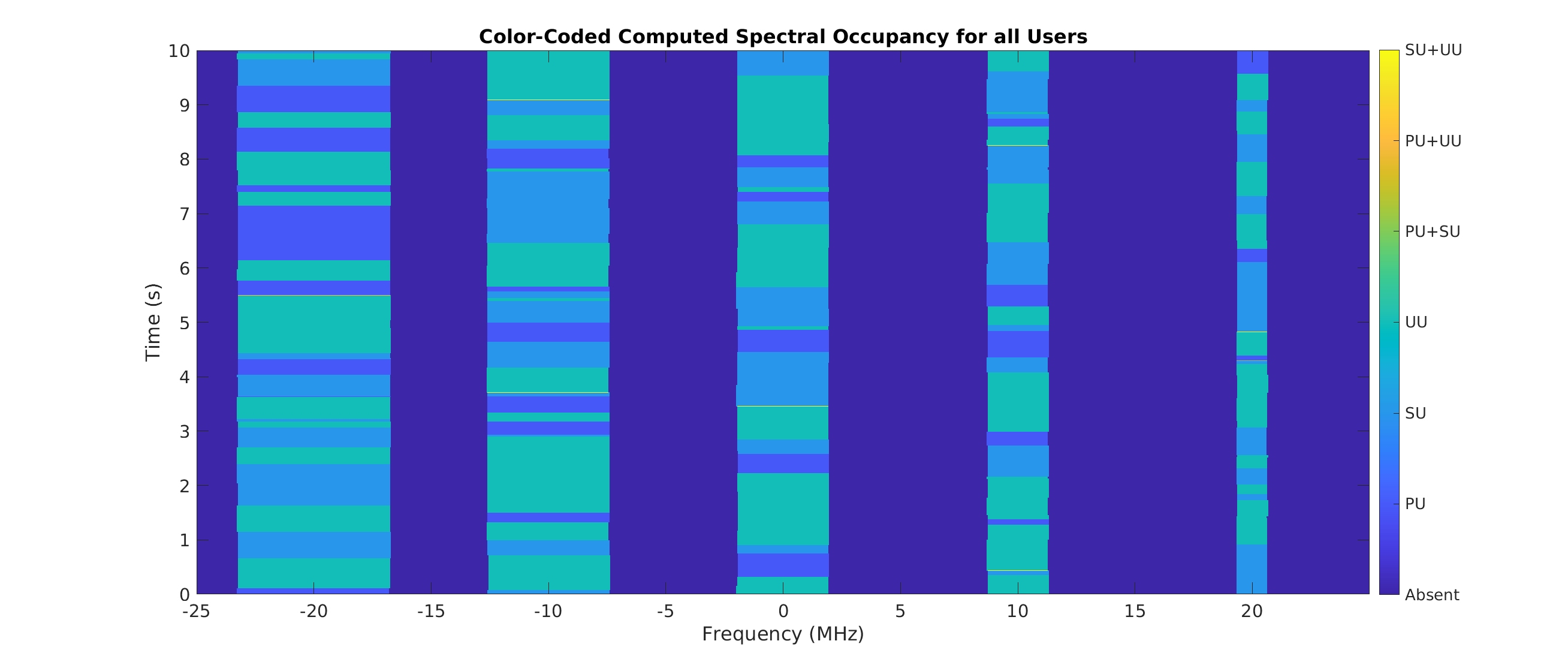
Figure 8: Masquerade. Designed to complicate spectrogram-based bounding-box detection by having many bounding boxes touch in the time dimension and have the same width in the frequency dimension.
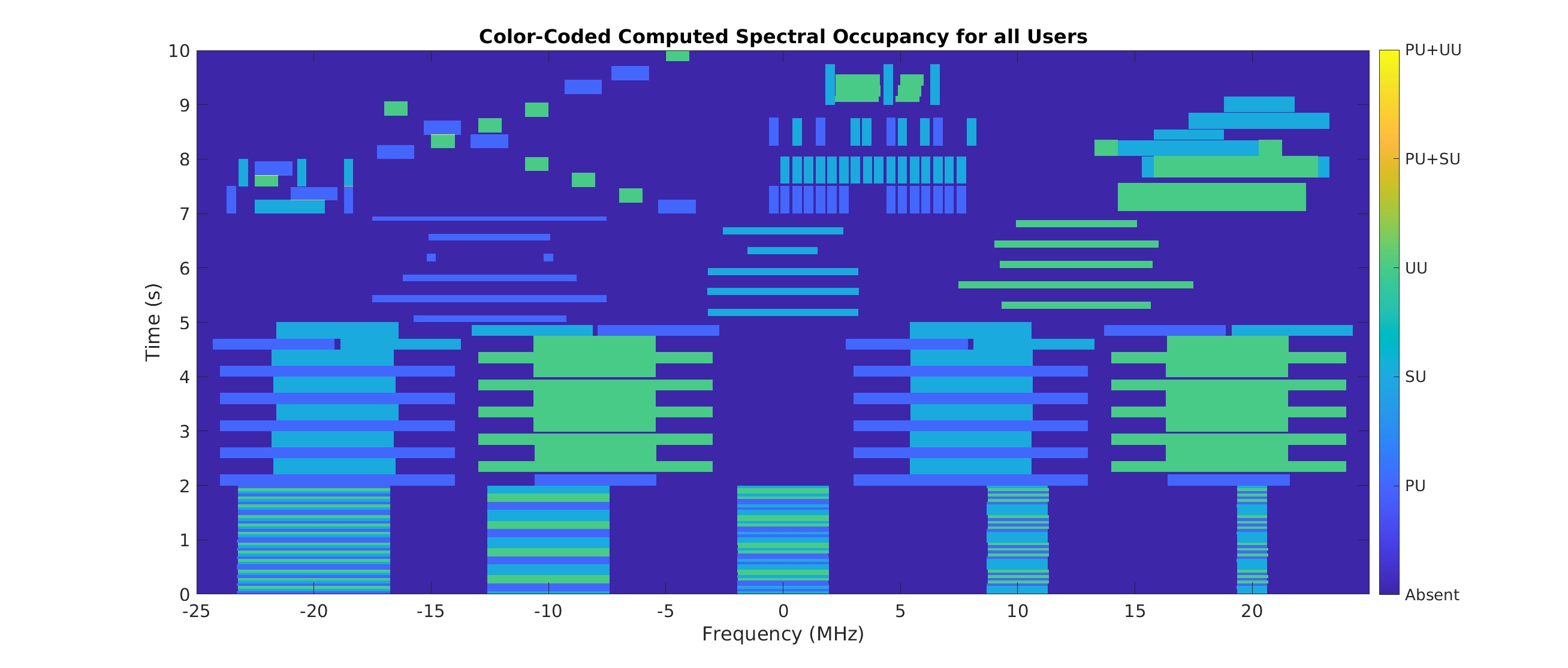
Figure 9: Sampler Plate. Designed to stress all approaches through rapid time variation, a wide range of signals, adjacent bounding boxes, etc.
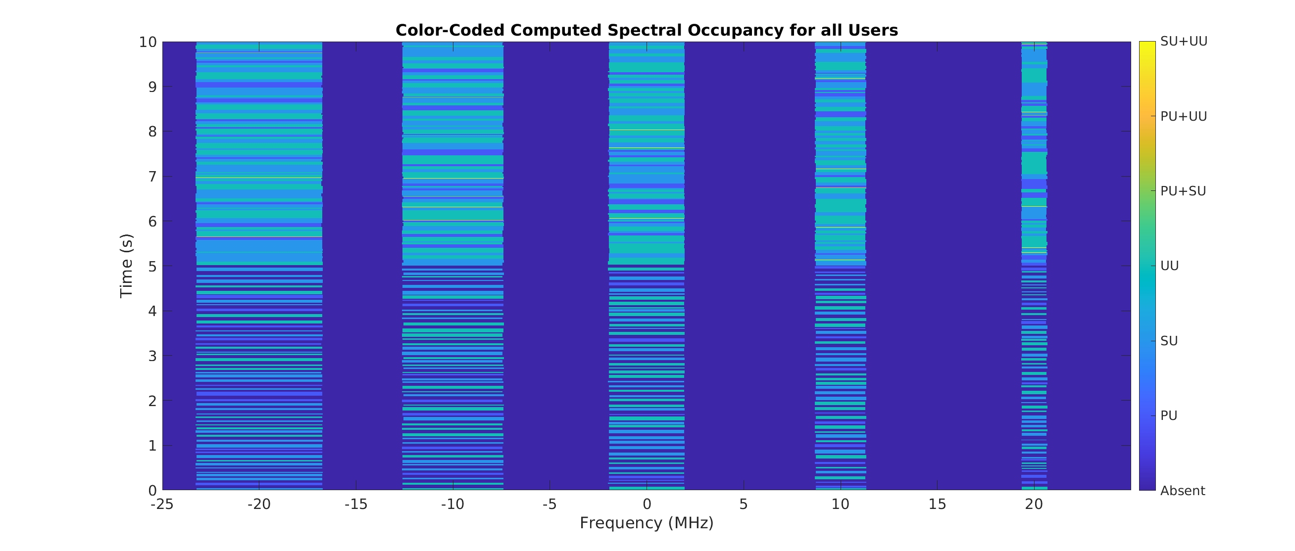
Figure 10: Bad Day. Introduction of discrete multipath channels. First half of this scene is like Tranquility with channels; second half is like Masquerade with channels.
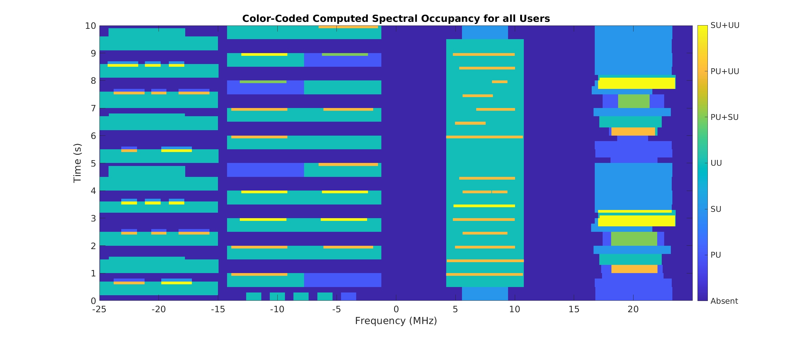
Figure 11: Emergency. Introduction of cochannel situations.
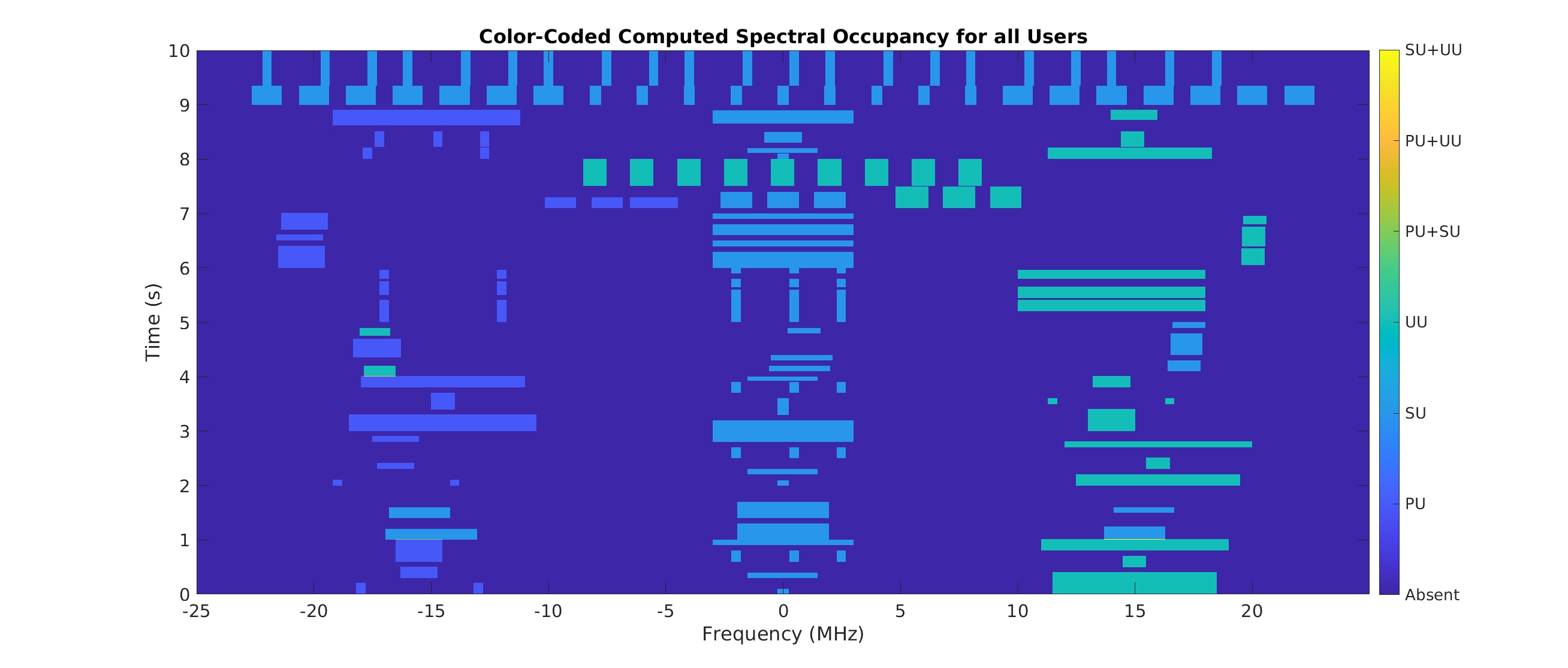
Figure 12: Scanners. Radar heavy with communication-signal confusors.
Direct inquiries to Dr. Chad Spooner at cmspooner@nwra.com.